Dr. Samantha Krukowski / Scott Nyerges

FormZ Basics
This tutorial covers several basic operations, including:
1) The FormZ screen layout
2) Drawing basic 3D shapes in FormZ
3) Viewing and rendering forms
4) Merging 3D forms
5) Adding projections and openings
6) Attaching shapes
7) Deleting objects
8) Changing surface colors and textures
9) Positioning and creating lights
10) A link to the FormZ manual
These basic operations will help you get started with FormZ. Where you go from there is up to you. Happy rendering!
Before you dig in: Save, save, save. Regularly. FormZ tends to freeze and you don't want to lose your work.
FORM Z SCREEN LAYOUT
The screen display below shows the main tools palettes.
You can find them under PALETTES > MODELING TOOLS, PROMPTS and SURFACE STYLES
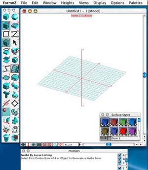
The work area shows a blue grid that is the reference plane. This is the plane you draw on. The x, y and z axes are in red. On the left is the tool palette arranged as a vertical strip of icons.
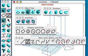
The tool palette: Modifiers
Tools shown in green boxes are called "operators." The other tools are called "modifiers." You select an operator tool to do something like create a rectangle and you use a modifier to decide that you want the rectangle to be projected in the third dimension to be a prism (or a cube). If you click on any of the tools and keep your finger down you will see a further palette of tools pop out to the right. To select one of those tools you keep your finger down and move the mouse to the right until the tool you want changes color (is highlighted). (This is like using the menus at the top of the screen.) When you release your finger then that tool is selected. It is ready to do its work. These palettes can also be dragged apart and moved around the screen.
Prompts window
At the bottom of the screen is a window called "prompts." This tells you exactly what to do as you use each tool. You can type in co-ordinates, separated by commas, or simply click on the work plane. If you position the cursor above one of the tools in the toolbox you will see a yellow rectangle telling you the name of the tool.
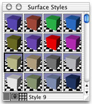
Surface styles window
On the right is a palette showing "surface styles." When you click on a surface style it becomes active. The object you create will have that surface style. Double click on the surface style to change it.
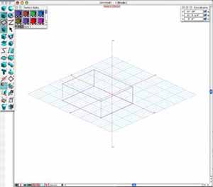
DRAWING BASIC 2-D AND 3-D FORMS
Draw some boxes on the reference plane by selecting the box tool (the second box from the top on the left column of the tool box) and the rectangle tool (just below the box tool). The box tool will allow you to draw both 2D and 3D forms, while the rectangle tool will also allow you to draw polygons and circles).
Point and click on the reference plane. Move the mouse in any direction and click again to complete the box. The height of the box is set in the heights menu at the top of the computer screen. Try selecting another height, or you can enter your own through the custom command of the heights menu.
Simple forms can also be created with the primitives tool (the first icon on the left column of the tool box). The objects created with this tool are parametric i.e. they have 'personalities' which can be altered. The primitives tool will allow you to draw boxes, pyramids, cylinders, circles and a torus (a big doughnut).
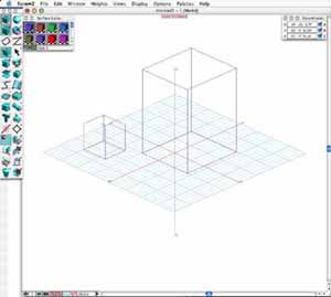
VIEWING AND RENDERING
You may want to view your objects from different angles. The View menu gives you various viewing options. Experiment with the five different angles at the top of the view menu. Try the different projections (axonometric, isometric, oblique and perspective and panoramic). For true plan and elevation views make sure that "axonometric" is selected.
You can also explore the different rendering systems built into form Z. There are 6 rendering options under the display menu.
You have explored the basic features of form Z. Try creating a more complex scene by following these steps:
MERGING 3D SHAPES
Note: Forms must overlap for these operations to work...
To cut one object out of another:
DISPLAYS > WIRE FRAME
PICK > OBJECT Choose the shape you want to have a space cut out of.
UNION > DIFFERENCE
PICK > OBJECT Choose the shape you wish to cut into the first form
DISPLAYS > QUICK PAINT, SURFACE RENDER, SHADED RENDER, etc. (to view results)
To join two objects:
DISPLAYS > WIRE FRAME
PICK > OBJECT Choose the first shape you wish to join to second
UNION
PICK > OBJECT Choose the second shape to be joined to the first.
DISPLAYS > QUICK PAINT, SURFACE RENDER, SHADED RENDER, etc. (to view results)
To create a third object from the intersection of two shapes:
DISPLAYS > WIRE FRAME
PICK > OBJECT Choose the first shape you wish to join to second object
UNION > INTERSECTION
PICK > OBJECT Choose second shape to be joined to the first.
DISPLAYS > QUICK PAINT, SURFACE RENDER, SHADED RENDER, etc. (to view results)
This basic procedure may also be used for many similar operations; explore them.
ADDING PROJECTIONS and OPENINGS
To add a rectangular projection from the surface of a shape:
DISPLAYS > WIRE FRAME
PICK > FACE Choose the face of the shape you wish to add the projection to.
INSERT FACE/VOLUME > 3-POINT RECTANGLE Draw your rectangle.
DISPLAYS > QUICK PAINT, SURFACE RENDER, SHADED RENDER, etc. (to view results)
You can also add projections of other shapes; play around with other forms in the 2D menu.
To cut a rectangular opening through a shape:
DISPLAYS > WIRE FRAME
PICK > FACE Choose the face of the shape you wish to cut the opening in.
INSERT OPENING > 3-POINT RECTANGLE Draw your rectangle.
DISPLAYS > QUICK PAINT, SURFACE RENDER, SHADED RENDER, etc. (to view results)
You can also add openings of other shapes; play around with other forms in the 2D menu.
TO ATTACH TWO SHAPES:
Draw two shapes in close proximity to one another.
PICK > FACE
Select the face of the first shape, then select the face of the second object. The two sides you choose must face one another.
ATTACH
Click on the form you wish to join to the second. The shapes are now joined.
You can also use the ATTACH tool to align two forms, so that that line up with one another on either the X, Y or Z axis. Play around with this.
TO DELETE AN OBJECT
Select TRASH CAN Click on the object you wish to delete.
MADE A MISTAKE?
APPLE Z = Undo
APPLE B = Redo
CHANGING SURFACE COLORS
Form Z provides a certain number of preset colors, which can be found in the SURFACE STYLES menu. To view this menu, go to DISPLAYS > SURFACE STYLES.
To change the surface color of the entire object:
DISPLAYS > WIRE FRAME
SELECT STYLE
PICK > OBJECT Choose the shape you wish to color
COLOR > COLOR Click on the shape you want to color
DISPLAYS > QUICK PAINT, SURFACE RENDER, SHADED RENDER, etc. (to view results)
To change the surface color of one side of an object:
DISPLAYS > WIRE FRAME
SELECT STYLE
PICK > FACE Choose the face of the shape you wish to apply color to
COLOR > COLOR Click again on the face you want to color
DISPLAYS > QUICK PAINT, SURFACE RENDER, SHADED RENDER, etc. (to view results)
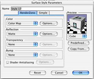
To create a new surface colors or pattern, or to modify existing styles.
Form Z will allow you to customize existing styles as well as create new styles.
Create new color: Go to DISPLAYS > SURFACE STYLES > NEW
Edit existing color: Go to DISPLAYS > SURFACE STYLES > EDIT
In either case, doing so will bring up the SURFACE STYLE PARAMETERS window. This is where you will modify your palette using color, reflection, transparency and bump. Play around with the possibilities.
Create a new surface style from a Photoshop image.
Form Z will also let you apply images that you have scanned into, or modified in Photoshop. To import these images (JPEG or TIFF):
DISPLAYS > SURFACE STYLES > NEW
Under the COLOR modifier, choose COLOR MAP
Click the OPTIONS button
Click the LOAD button. Locate your image and select it. Click OK. This will return you to the PARAMETERS menu.
NAME your new style. Click OK again. This will return you to the STYLES window. Click OK.
To view these special surfaces, you must choose DISPLAYS > RENDER ZONES
LIGHTING: MOVING LIGHTS
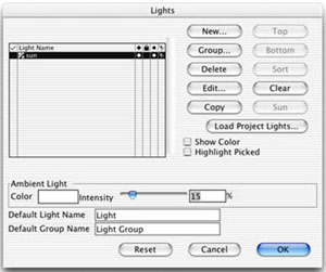
To open, go to PALETTES> LIGHTS. The LIGHTS PALETTE looks like this:
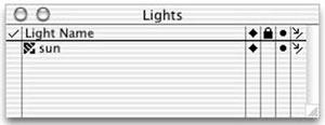
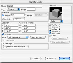
Each project starts with one light — the sun — already in
place. You will see this listed as LIGHT 1 in the LIGHTS PALETTE. To rename,
double-click on LIGHT 1, which brings up the LIGHT PARAMETERS window.
Next to NAME, type “sun.” Click OK.
TO VIEW THE POSITION OF ANY AND ALL LIGHTS:
1. Scale VIEW to 50% or 25%.
2. To make the sun (or any light) visible, click on the black diamond
column on the LIGHTS PALETTE. Black diamond = visible, able to be manipulated.
Gray diamond = “ghosted” (visible, but not editable). No diamond
= hidden.
3. You can choose to move you lights in one of three ways: source (black
circle), fall point (arrow point) and entire light (circle, line, arrow
point).
4. To move a light, first make sure the black diamond is visible in the
LIGHTS PALETTE beside the light you wish to move. Choose PICK > MOVE
Click on source, fall point or entire light (point to be moved is highlighted
in red.) As you maneuver in 3D space, you’ll need to refer to different
viewpoints to make sure you light is falling correctly.
5. To adjust intensity and color of the light: OPTIONS > LIGHTS. COLOR
box brings up a color menu allowing you to modify color of lights; INTENSITY
allows you to adjust intensity (less is better)
LIGHTING: CREATING NEW LIGHTS
1. OPTIONS > LIGHTS > NEW
2. Brings up the LIGHT PARAMETERS menu. TYPE allows you to choose from
distant (a second sun), as well as point, cone, projector, area, etc.
COLOR allows you to adjust color of light.
3. One you NAME your light and set the basic parameters, it will appear
in the LIGHT WINDOW and can be adjusted as you would the sun.
SUPPLEMENTAL INFO
Modifiers
3D Extrusion: Any shape you draw in plan will be projected vertically
as thin walls. If the plan shape is closed then the box will have a top.
3D Converged: Any shape you draw in plan will form sides that slope up
to a point.
3D Enclosure: Any shape you draw in plan will be projected up to form
walls with a particular thickness.
Insert Face: If you draw a shape on an existing surface then it will form
a 3D projection from that surface.
Insert Opening: If you draw a shape on an existing surface then it will
create a hole right through the object.
Operators
Rectangle: This is for drawing rectangles defined by their top left and
bottom right corners.
Rectangle 3 Points: To draw a rectangle, but you first draw a straight
line at the angle you want.
Polygon (N): For drawing regular shapes, such as hexagons.
Circle: For drawing circles.
Vector Line: For drawing closed or open ended shapes with straight edges
at any angle. You double click to finish drawing.
Cube Primitive: For drawing parametric cubes.
Cone Primitive: For drawing parametric cones.
Cylinder Primitive: For drawing parametric cylinders.
Sphere Primitive: For drawing parametric spheres.
Spline Curves: For drawing smooth curves in any direction on a plane.
Arc: For drawing segments of a circle, clockwise or counter-clockwise.
Pointer or Arrow: For selecting objects to move or otherwise alter.
Edit Controls: For transforming the controls of a parametric object.
Edit Surface: For directly changing the shape of a parametric object's
surface.
Sphere: For drawing spheres
Union » For merging two 3D objects into one.
Intersection « For creating a new object that is formed by the intersection
of two existing overlapping objects.
Difference: For creating a new object that is formed by subtracting one
object from another.
Move: For dragging an object to a new position.
Rotate: For rotating an object about a point.
Scale XYZ: For making an object uniformly bigger or smaller.
Color: For assigning a surface quality to an object.
Texmap: For assigning a texture map (such as brickwork) to a surface.
Decal: For pasting a scanned image to a surface.
Delete: For removing objects.
Window Tools
![]()
Along the bottom side of the work area window is a series of window tools.
XYZ Reference Planes: This is for adjusting where the blue grid (reference
plane) is located in the work area. It can be in the XY, YZ or ZX direction.
Ignore ARBITR for the time being. The reference plane is important as
that is the surface you draw on.
Perpendicular Switch: For deciding whether you are drawing on or at right
angles to the reference plane. It should appear white (off).
Define Reference Planes: For defining and moving the reference plane.
Grid Snap: For drawing objects so that their corners coincide with points
on the reference plane grid. White is off.
Direction Snaps: For precision in creating objects. Should say "NONE."
Object Snaps: As above
Zoom and Pan: For making the objects you are drawing appear larger or
smaller on the screen. Select RESET if you get confused.
Views For changing your angle of view dynamically. Follow instructions
in the Prompts window.
Zoom Factor: This displays the zoom factor of the main workspace.
Rendering Types
Wire Frame: All edges of objects are visible and objects appear transparent
Quick Paint: Objects appear as a series of surfaces. This is useful for
viewing a single object that is very simple. For more than one object
the surfaces becomes muddled. It is a quick renderer.
Hidden Line: Shows all visible edges of objects. Draws objects as made
up of white surfaces. Useful if you want to output the image to a pen
plotter.
Surface Render: Shows surfaces of objects in uniform color. Shows shadows,
but no subtle gradations across surfaces.
Shaded render: Surfaces appear smooth, show simple reflective properties,
and there are shadows. Curved surfaces are smooth. Has anti-aliasing-straight
lines do not appear jagged.
RenderZone: As for shaded render, but with surface transparency, reflections,
and sophisticated surface properties. This is the slowest renderer, but
can give spectacular photorealism.
NEED MORE HELP? Click here
to download a .PDF file of the FormZ manual
More resources:
FormZ
support gallery